


BERLIN pilots have the potential to be expanded with the coupling of other energy carriers
The BERLIN project aims to develop pilots in the participating countries that combine Photovoltaic (PV), Battery Energy Storage System (BESS), and Demand-Side Management (DSM) technologies, under the microgrid concept.
One of these actions is the Cyprus pilot, which will convert the existing Photovoltaic Technology Laboratory of the University of Cyprus (UCY) into a Living Lab nanogrid. Specifically, the Cyprus pilot aims to increase the levels of self-consumption (proportion of energy locally produced that is locally used) and self-sufficiency (proportion of energy locally used that is not imported). In addition, in order to satisfy the energy needs of the buildings, it is desired to generate and store electricity for the charging of Electric Vehicles (EVs).
Although, the existing PV-BESS-DSM configuration can meet the aforementioned targets to a large extent, energy storage can become even more effective with additional energy carriers that are not limited in terms of capacity and duration. This is because energy storage in batteries is primarily suitable for a few hours/days. However, supply and demand in a PV-based system configuration vary significantly between seasons. Specifically, in terms of supply, electricity generation from the solar PVs is very high during summer and high during midseason, but low during winter. In terms of demand, electricity consumption is very high in the summer and winter, and moderate during midseason.
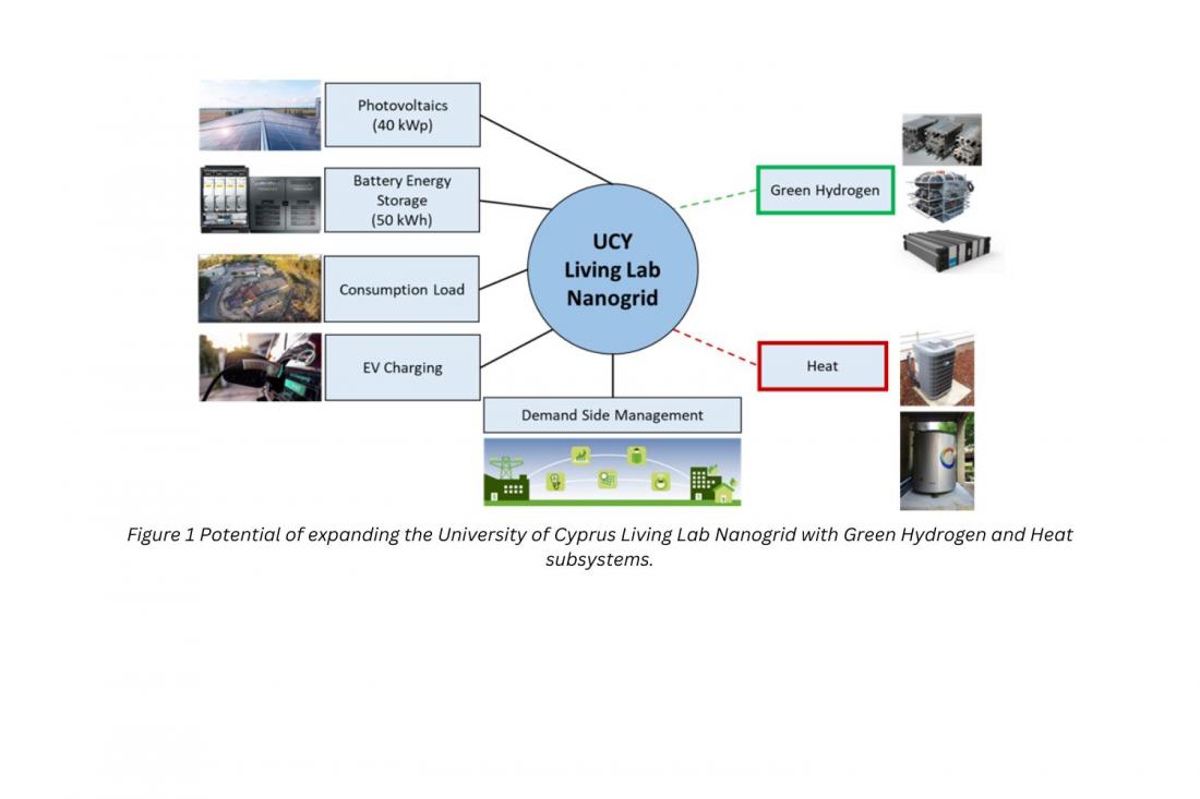
Therefore, different types of useful energy are required, such as electricity (for both buildings and EVs), space heating, space cooling, and domestic hot water. The aforementioned targets can be materialized more effectively throughout the year with the further coupling of the PV-BESS-DSM nanogrid system with other energy carriers, such as green hydrogen and heat. This is because green hydrogen and heat can provide additional capabilities to the nanogrid system, such as power-to-gas-to-power, power-to-heat, and seasonal energy storage. These can in turn allow an increase of the PV subsystem capacity without the need of (a) increasing the BESS capacity, (b) curtailing electricity (i.e., wasting available output), or (c) exporting electricity to the central power grid.
A Green Hydrogen subsystem, consisting of electrolyzer, hydrogen storage and fuel cell units, can be coupled to the PV-BESS-DSM nanogrid system to utilize excess electricity that cannot be stored in the BESS. Generated green hydrogen can be stored for months and therefore it can be used from one season to the next one; this helps solving the difference between supply vs. demand between seasons through seasonal energy storage. Fuel cell units also generate heat as a by-product, in the form of hot water/steam, which can be used to cover partly or fully the space heating and domestic hot water demands of the pilot buildings.
A Heat subsystem may consist of several technologies, with the most promising being an electric vapor-compression heat pump and thermal energy storage combination. In this manner, excess electricity from the solar PVs can be converted to heat through highly efficient heat pumps operating at coefficient-of-performance (COP) values of 3-7. This means that space heating, space cooling, and domestic hot water demands can be satisfied with the consumption of significantly less electricity, and therefore remarkably lower carbon emissions and operational costs compared to conventional technologies, such as electric (coil) heaters and oil-fired boilers.
The coupling of energy vectors and combination of short- and long-term energy storage can improve the overall energy efficiency and cost effectiveness of the nanogrid system, by providing advanced flexibility, load balancing, grid stability and smart operation capabilities.
A schematic configuration of the UCY Living Lab nanogrid with the proposed further coupling of Green Hydrogen and Heat subsystems (shown in green and red rectangles, respectively) is given in Figure 1.